
Demag CC 2800-1 Blog update
Prototype perfection
In one of our previous blogs, we had a look at all our different builds and configurations. Most of these setups are tested in 3D design, in combination with hardware parts and previous constructed models, to calculate the strengths, weights and angles necessary for our ambitious CC 2800-1 project. But 3D only gets us so far. Today we will be looking at the other three major design stages, starting with the 3D printed prototype.
3D printed prototype
.jpg)
Modern 3D printing allows us for rapid prototyping of all parts into physical objects that we can touch, assemble, and inspect. While such an early prototype is not a true representation of die-cast metal connections and strengths, it does allow for visual comments and function design. Testing whether you can connect the crawlers without turning your hand in impossible angles, for example, is difficult to assess on a 3D model. This is where our printed prototype comes in.
Another example for its use is testing all hardware parts, such as the reeving of rope, nuts and bolts, cylinders, and photo-etch inlays. Hardware parts are pieces that are not shaped in our own molds, but are aquired by our purchasing department. The 3D printed prototype is a ‘live’ sample, meaning that we update it with every feedback round until we are satisfied. After a final check, we start with shaping our die-cast molds to form our first metal sample.
Metal sample
After several weeks of cutting shapes for our die-cast and plastic molds, we run a first ‘test-shot’. This is the first time we pour liquid metal in our molds to shape our ‘trees’:
.jpg)
These ‘trees’ are the frames that hold several pieces together. Some pieces are so large that they have their own tree, such as the boom part pictured below. Here you can clearly see how an unpolished piece comes fresh out of our molds. The excess metal needs to be trimmed and polished before we can start our decorating process.


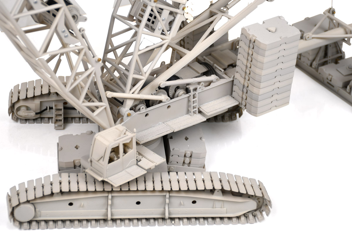
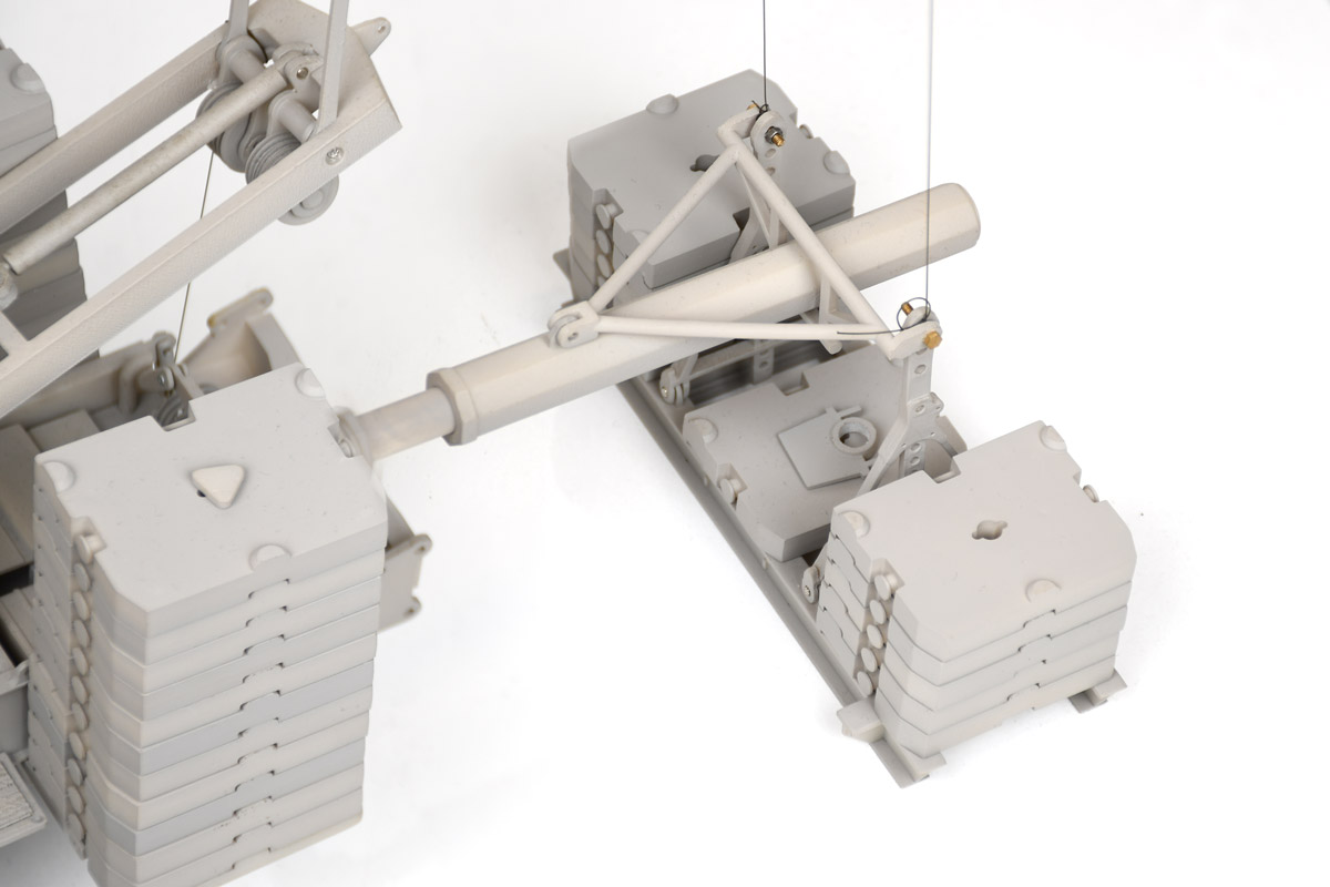
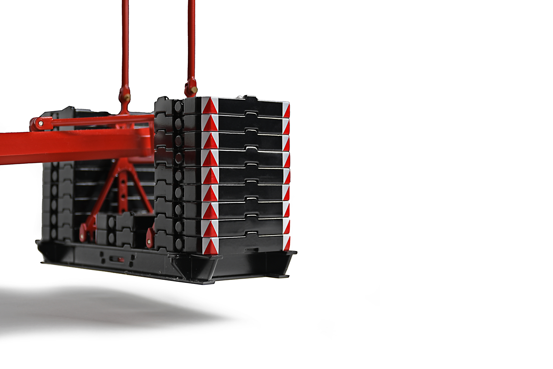
When we trimmed and polished about 3.500 parts, we have enough to assemble two or three models. Especially our tracks take up allot of time to manually trim, polish and connect each individual pad. We apply a double layer of white paint to test paint thickness margins:


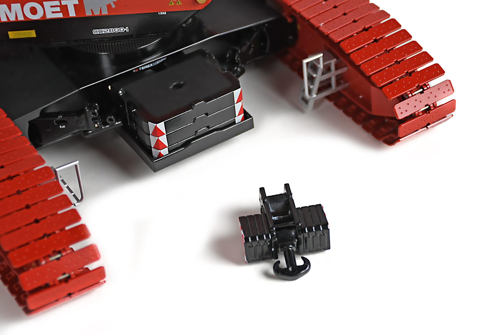
After many days and nights of getting everything ready, we proudly assemble our metal samples. In the process of assembling, we already encounter many improvements, such as the margins between connections and small defects in our molds. We can also test the strength of the final model by hanging weights on the hook and adjusting the distance of our stinger and total number of counterweight plates. Because metal samples do not allow us to print new versions on the fly, we shave and trim parts to test the correct thicknesses. We will need to modify the molds several times to get everything right. When we are confident that our improvements resulted in the perfect model, it’s time for our first colored sample!
Colored sample
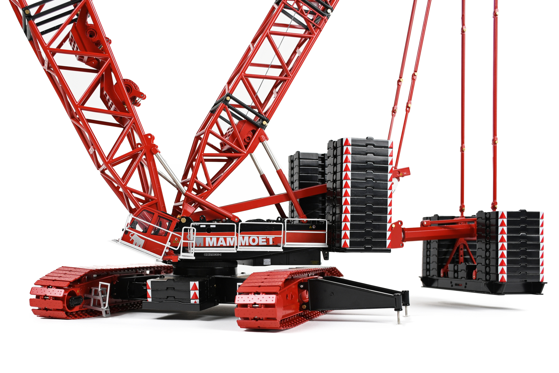
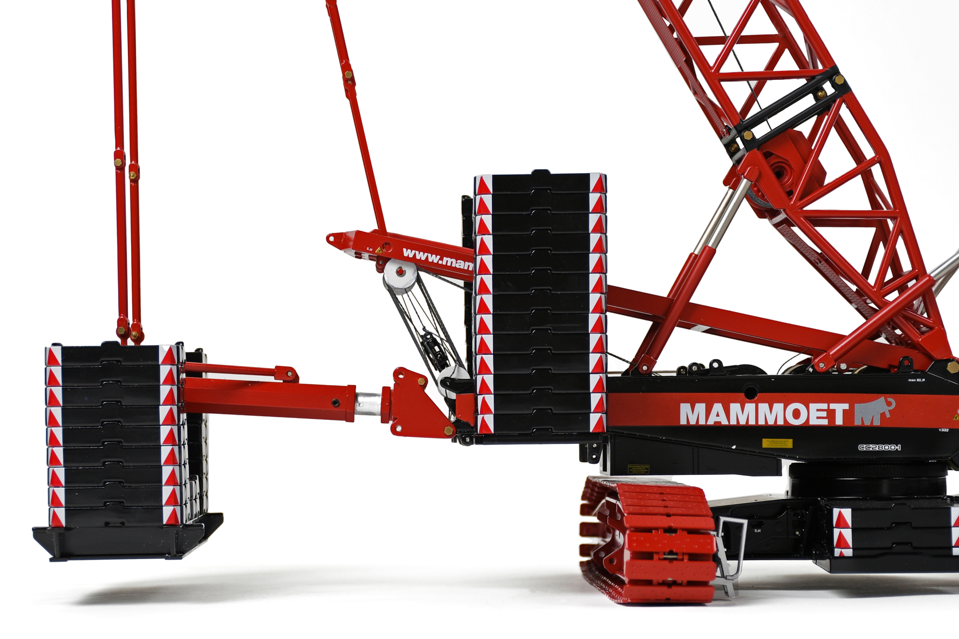
It’s here! The fruits of our labour. The colored sample of our Mammoet Demag CC 2800-1 really comes close to a finished product. Most of the finetuning of our metal sample has been incorporated in the colored sample, while some adjustments require more time. But for now, the most important goal of our colored sample is testing and preparing the decoration techniques. A black and red Mammoet model has different paint thicknesses than a yellow Demag version. While it may only vary 0.5 mm in thickness, it has great effects on all sheaves, track connections and boom pieces. This is where our colored sample comes in handy.
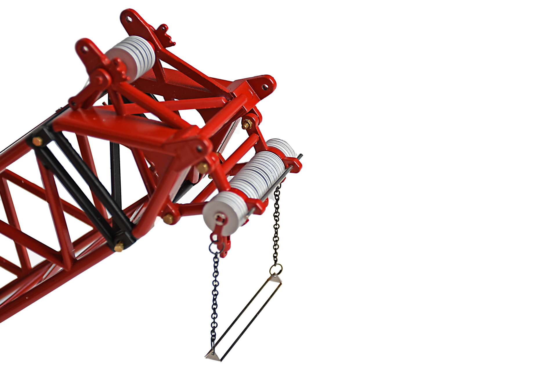
We also test customer specific decorations. One example of a challenging decoration is pictured below.
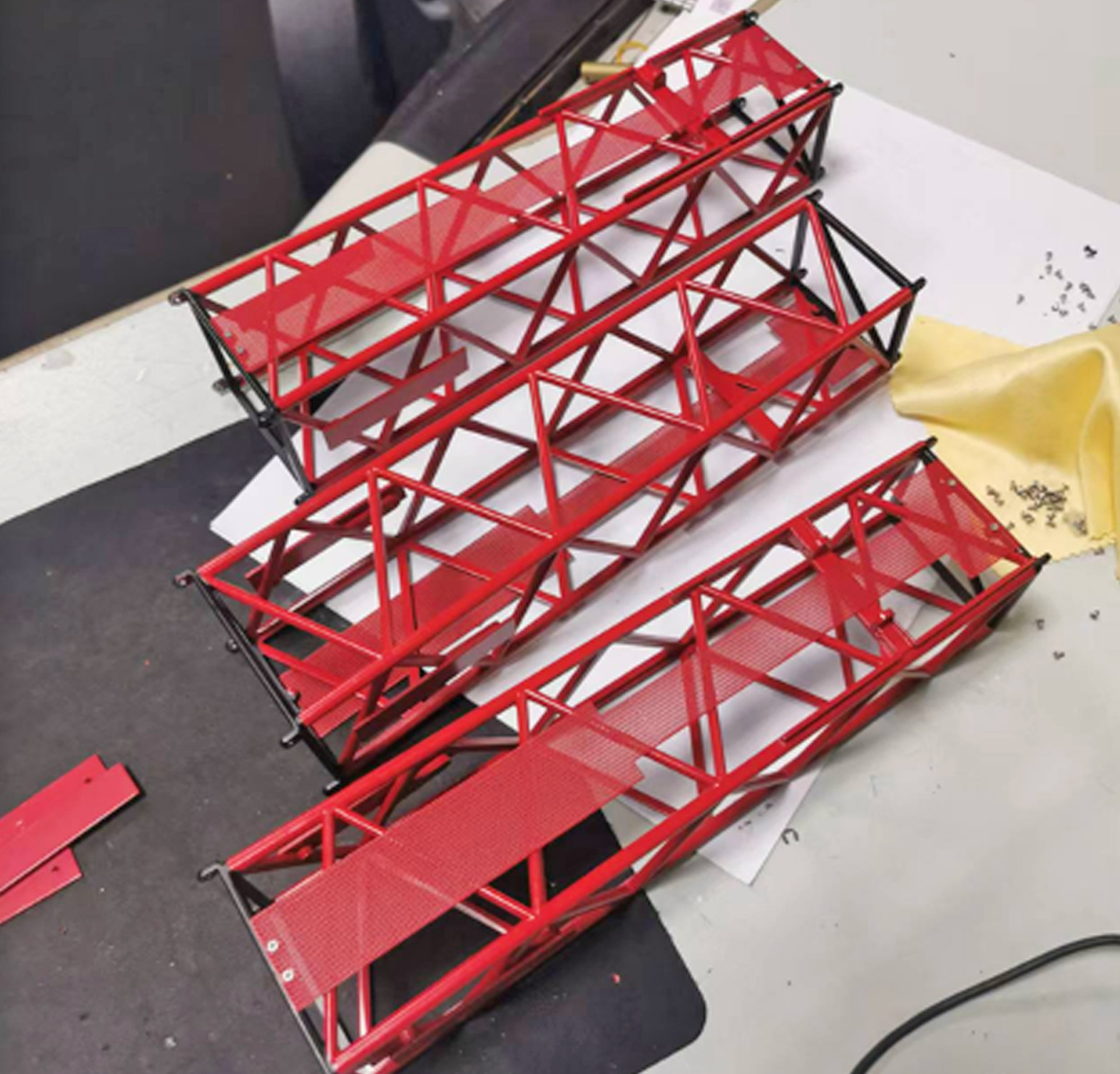
Many of you will recognize the red booms with black endings at the connection. While this may seem like a simple two-colored piece, many manufactures have struggled with this. Simply ‘dipping’ the ends in paint is not an option due to paint thickness requirements. And pad printing will not get all around the connections. Mask spraying is most commonly used, however as collectors might notice, this can result in quite some overspray. We will not disclose our exact technique, but a combination of several options gave us a crisp result.
Besides testing the model itself, this sample also allows us to start working on a proper instruction for our assembly and decoration lines, and a build manual for customers to configure their CC 2800-1. Before we start mass production, we design our packaging and put our colored samples trough several official drop-tests and inspections.
Curious about the end result of the model? We have the first images of the Mammoet version for you!
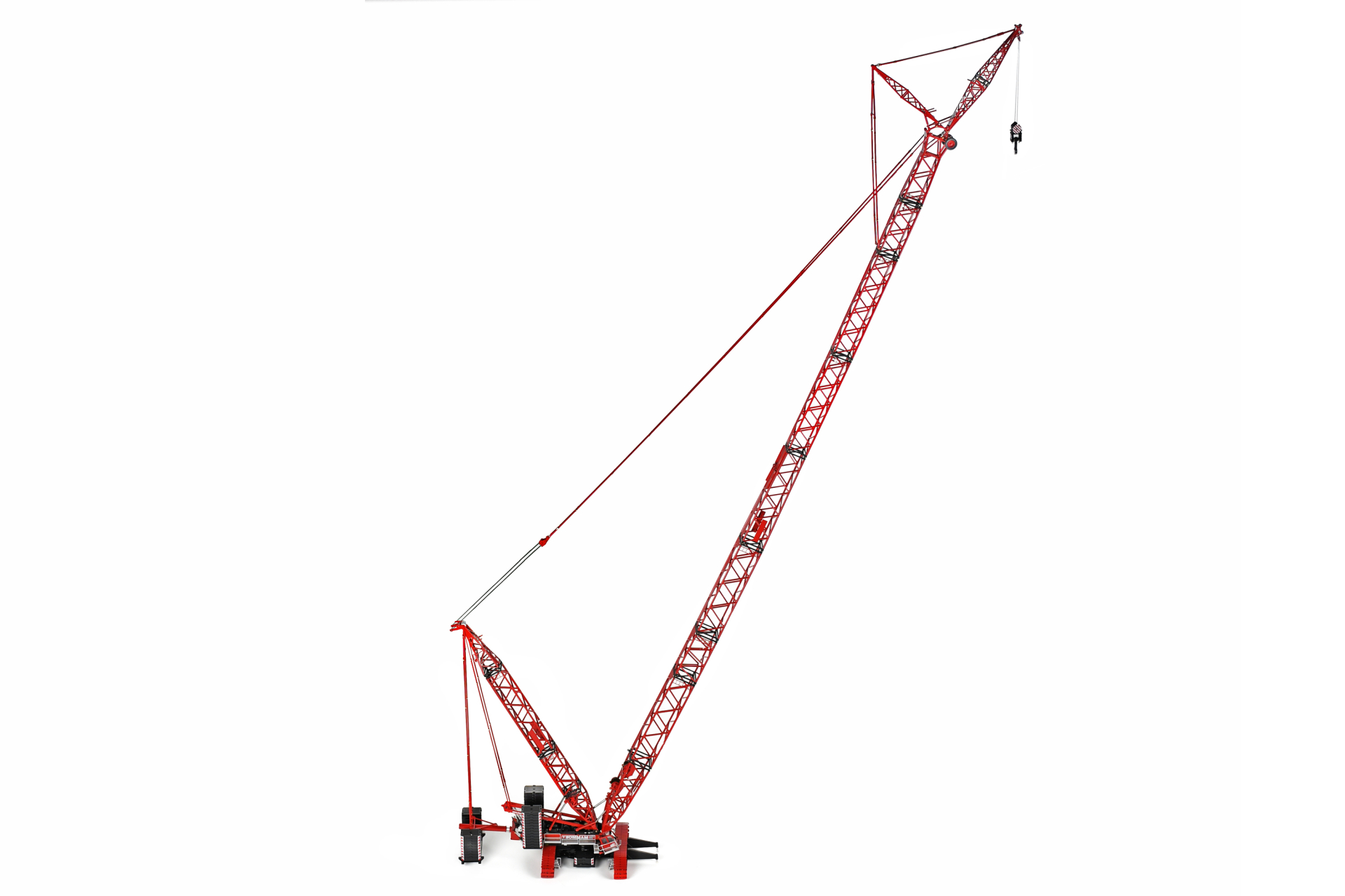
Pre-order the Tadano CC 2800 Legacy Model Pre-order the Demag CC 2800 Pre-order the Mammoet CC 2800